Learn how to build a Bluetooth-controlled LED matrix display using Arduino and a smartphone. Send custom scrolling messages wirelessly! Includes features, components, circuit diagram, how it works, and complete code.
Introduction
Looking to spice up your DIY skills with a fun and practical project? A Bluetooth-controlled LED display is the perfect entry into wireless electronics. It allows you to send custom scrolling messages from your smartphone to a vibrant LED matrix — a great addition to your home, shop, or tech corner.
In this guide, we’ll show you exactly how to build your own wireless LED display using Arduino, the HC-05 Bluetooth module, and a MAX7219-based LED matrix. Whether you’re a hobbyist, a student, or just someone who enjoys creating cool stuff, this project is for you.
Features of the Bluetooth-Controlled LED Display
Let’s take a look at the powerful and exciting features of this DIY project:
- ✅ Wireless Control: Send messages wirelessly from your Android phone using Bluetooth.
- ✅ Custom Scrolling Text: Display any message with smooth horizontal scrolling.
- ✅ Expandable Display: Add multiple 8×8 LED matrices for longer messages.
- ✅ Portable and Compact: Runs on a simple 5V power source.
- ✅ Easy to Build: Beginner-friendly with reusable components.
- ✅ Real-World Applications: Use as a welcome board, event notifier, or even a smart nameplate.
Components Required
Before we start building, here’s what you need:
| Component | Quantity | Description |
|---|---|---|
| Arduino UNO/Nano | 1 | Main microcontroller |
| HC-05 Bluetooth Module | 1 | For wireless communication |
| MAX7219 LED Matrix Display | 1–4 | For scrolling messages (8×8 per unit) |
| Jumper Wires | As needed | For connections |
| Breadboard (Optional) | 1 | For prototyping |
| Android Phone | 1 | To send messages |
Circuit Diagram and Connections

Here’s how you connect everything together:
MAX7219 LED Matrix to Arduino:
| MAX7219 Pin | Arduino Pin |
|---|---|
| VCC | 5V |
| GND | GND |
| DIN | D11 |
| CS | D10 |
| CLK | D13 |
HC-05 Bluetooth Module to Arduino:
| HC-05 Pin | Arduino Pin |
|---|---|
| VCC | 5V |
| GND | GND |
| TXD | RX (D0) |
| RXD | TX (D1) via voltage divider |
💡 Tip: Disconnect the HC-05 while uploading code to avoid communication conflict.
How to Make a Bluetooth-Controlled LED Display
Follow these step-by-step instructions to build your own project:
1. Assemble the Circuit
Use jumper wires to connect the LED display and Bluetooth module to the Arduino as per the diagram above.
2. Install Libraries in Arduino IDE
Go to Sketch > Include Library > Manage Libraries, then search and install:
MD_ParolaMD_MAX72XXSPI
3. Upload the Arduino Code
cppCopyEdit#include <MD_Parola.h>
#include <MD_MAX72XX.h>
#include <SPI.h>

#define HARDWARE_TYPE MD_MAX72XX::FC16_HW
#define MAX_DEVICES 4
#define CS_PIN 10

MD_Parola display = MD_Parola(HARDWARE_TYPE, CS_PIN, MAX_DEVICES);

String inputString = "";
bool stringComplete = false;

void setup() {
  Serial.begin(9600);
  display.begin();
  display.setIntensity(5);
  display.displayClear();
  display.displayScroll("Welcome!", PA_LEFT, PA_SCROLL_LEFT, 100);
}

void loop() {
  if (stringComplete) {
    display.displayClear();
    display.displayScroll(inputString.c_str(), PA_LEFT, PA_SCROLL_LEFT, 100);
    stringComplete = false;
  }

  while (Serial.available()) {
    char inChar = (char)Serial.read();
    if (inChar == '\n' || inChar == '\r') {
      stringComplete = true;
    } else {
      inputString += inChar;
    }
  }

  if (display.displayAnimate()) {
    display.displayReset();
  }
}
4. Set Up Your Phone
- Pair your phone with HC-05 (default PIN: 1234)
- Use Serial Bluetooth Terminal (Android app)
- Type your message and press Enter
How It Works
Let’s break down the working principle of this wireless LED display:
- Bluetooth Communication: Your Android phone sends serial data over Bluetooth.
- HC-05 Receives Data: The Bluetooth module transmits the message to Arduino via UART.
- Arduino Parses Input: Arduino stores the message in a string.
- Display Driver: The MD_Parola library handles the scrolling and character rendering.
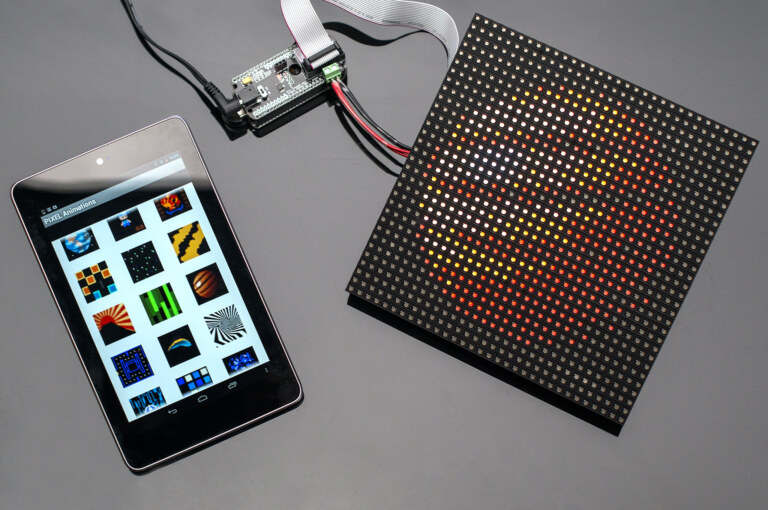
- LED Matrix Output: Your message is animated across the LED modules.
It’s like a mini billboard you can control from your pocket!
Real-Life Applications
This project has a lot of practical uses:
- Smart Home Display
- Shop Welcome Signs
- Event Name Boards
- School Projects
- STEM Learning Activities
- Desk Nameplate
Safety and Precautions
- Use a voltage divider for HC-05 RX pin to avoid damaging it with 5V TX from Arduino.
- Disconnect HC-05 before uploading code to avoid serial port issues.
- Avoid powering the LED matrix from Arduino’s 5V pin if using more than 2 modules — use an external 5V adapter.
Best Apps for Sending Messages
Here are a few trusted Android apps you can use to communicate with your display:
| App Name | Features | Download |
|---|---|---|
| Serial Bluetooth Terminal | Free, Simple, Reliable | Play Store |
| Bluetooth Terminal | Lightweight, Great UI | Play Store |
Frequently Asked Questions (FAQs)
Q1: Can I use this with iPhone?
No. The HC-05 Bluetooth module uses classic Bluetooth which is not supported by iOS. For iPhone compatibility, use BLE modules like HM-10 or ESP32.
Q2: How many LED matrices can I connect?
You can chain up to 8 modules easily. Just increase MAX_DEVICES in code and ensure power supply can handle the load.
Q3: Why is my display not scrolling the message?
- Check if the libraries are correctly installed.
- Confirm wiring, especially DIN/CS/CLK.
- Make sure the message ends with a newline (
\n) character.
Q4: Can I use an ESP32 instead of Arduino?
Absolutely. ESP32 has built-in Bluetooth and Wi-Fi, making it a great upgrade for future versions.
Q5: What power source should I use?
- For up to 2 LED matrices: Arduino’s 5V pin is fine.
- For 3+ modules: Use a 5V 1A adapter or USB power bank.
Final Thoughts
Building your own Bluetooth-controlled LED display is a fun and rewarding way to explore wireless technology and microcontrollers. It’s beginner-friendly, budget-friendly, and extremely versatile. Whether you’re creating a custom display for your desk, events, or home automation, this project blends creativity with real tech skills.
You now have everything: the circuit, the code, the components, and the confidence.
If you face any issues building this project, feel free to ask in the comments below!
👉 Want more cool Arduino projects? Check out our DIY Electronics Project Hub.
Source
photo by Adafruit Industries